The Omron_remote_control program is designed to exchange information
between an Android smartphone and the OMRON family of controllers (CS1, CJ1,CJ2, CP1H, CP1L, NJ...).
Communication is carried out by means of the computer on which the management software server functions.
Communication between the computer and the controller is carried out over an Ethernet (or Ethernet/IP) network(basic version) .
The connection between the smartphone and the computer is carried out via the Internet (MQTT broker) (basic version).
This application has the ability to form a connection between the smartphone and the controller
also over Bluetooth and Wi-Fi, however, these modes are auxiliary modes < BR>
only for executing commands to read/write controller variables.
There are two possible ways to connect the computer to the controller.
According to the first method, communication between them is carried out using the protocols
Ethernet or Ethernet/IP, while using the DLL developed by the author -
Ethernets.dll .
The second method uses the reworked and embedded in the main program
features of the CX-Server system software package (OMRON).In this case, the communication between the controller
and the computer is carried out via USB,Ethernet , Ethernet/IP , RS232/485 protocols.
The app is designed for the following technologies:
- IoT;
- Remote control;
- Remote diagnostics.
- Start-up and adjustment work on the object, when the adjuster
must be away from the control cabinets of the object;
- Generating relevant information about the object for
service personnel and management of the enterprise.
The following functions are implemented on the smartphone :
- Setting the parameters to the required exchange values
information between the smartphone and the controller;
- Write / read an entire word of memory by the user's command;
- Write / read a bit of memory by the user's command;
- Cyclic reading of variables from different memory zones
controller (auxiliary mode);
- Cyclic reading of variables of a single memory zone
controller (main mode);
- Execution, user-defined or preset,
FINS strings;
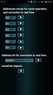
- Cyclic control of the specified memory variables
the controller is set to the minimum and maximum limits in
real time with the generation of signals at
going beyond the limits-Alarms (controlled limits
set by the user). If necessary
automatic generation of an E-mail to a user with
a failure message at the required internet address.
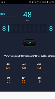
- Quick variable value adjustment – memory word
of the controller, in real time;
- Quick adjustment of the value of a variable – bit memory
of the controller, in real time;
- Installing and working with controller bit objects
(the installation is performed once when you first log in to
The program and may not change further);
- Working with word bits – Reading / writing graphic
displaying word bits-similar to the SwitchBox program
(OMRON), in real time;
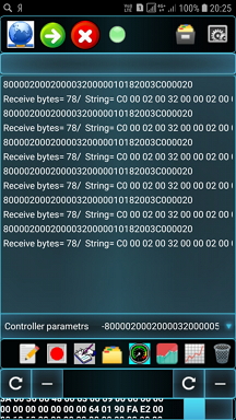
- Display of variables accepted in the loop in a separate
Memo in real time, with the ability to write
add the Memo content to the file and select the file content in
Memo.
- Display of 6 variables on the indicator board with
the ability to generate color signals, if the values
variables go beyond the required limits in real
time scale;
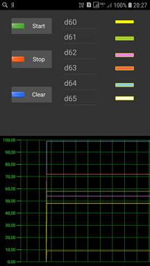
- Formation of waveforms of 6 variables in real
time scale. Period time =0.5...1 sec;
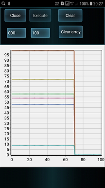
- Formation of static graphs of 6 variables in
in real time . Period time =0.5...1 sec.
Recording time-up to 4 hours
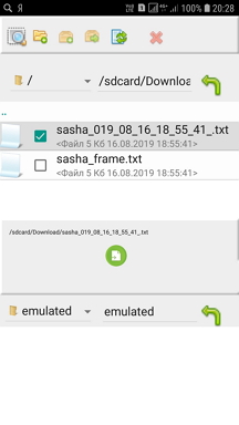
- Working with the built-in file editor;
- Receiving the OEE parameters of the object operation from the controller and forming
graphical display of these parameters in real time;
- Forming a command to execute the Log-log entry
the required parameters in the computer memory file in different
formats;
- Formation of an autonomous control mode in the computer
parameters with the generation of an alarm signal at the operator's post, with
generating an E-mail message about the failure at the required address;
- Generating notifications to the computer user in the format
Windows 10, if it runs on this operating system;
- Offline verification of the correct formation of the Internet
exchange addresses using the built-in Ping mode;
- Read / write variables of the Trajexia motion controller
(OMRON). etc.
1.2 . The Omron_remote_control program consists of 2 parts:
- Omron_remote_control. apk-implemented on a smartphone;
- Omron_universal_server.exe -implemented on a computer;
The application is developed in DELPHI XE10 (Embarcadero) using 2 software
components from other manufacturers.
Obviously, this application can be easily expanded and adapted to the specific
requirements of a particular Customer.
This application is paid. The cost of the app (without listing) is $ 50 USA.
The cost of the application (with a listing) is equivalent to the salary of a programmer.
level for 3 months.
If you have any questions about purchasing the program, please contact the author at
E-mail ab.ryss@yandex.ru or go to the Samsung Galaxy Store-app Omron_Remote_Control.
For a more detailed description of this application, please visit
www.mrplc.com Section Omron-Download-Utility-Omron_control.
1.3. The application was tested at sites in Ukraine and India
(pipe rolling mills of the HPT series) under the control of operating
systems Windows XP, Windows 7, Windows 10 and on
Samsung, Phillips smartphones running the Android 5.0 ... 8.0 operating system.
This application can be easily modified to exchange information with controllers
other manufacturers.
So on the basis of this application, a similar was developed
software for communication between a smartphone and controllers of the
family Yaskawa MP2300, while the connection between the computer and the controller was carried out
using the Modbus/TCP protocol.
1.4 Obviously, the user does not need to have any special knowledge about setting up computer networks.
The corresponding smartphone and computer only need to be connected to the Internet.
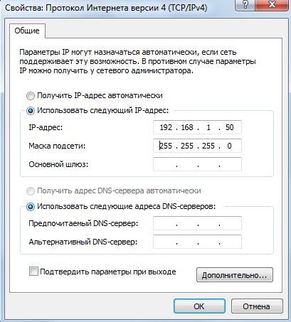
By default, to communicate with the controller over Ethernet ( Ethernet/IP), the computer must be configured
to the address 192.168.1.50.
By default, the controller must be configured to address 192.168.1.2. Network addresses of the computer
and the controller settings are configured according to the OMRON rules.
It is also obvious that the corresponding addresses are
subject to change.
Before starting the exchange of information, the corresponding networks must be enabled,
the smartphone must be turned on, the computer and the controller, the computer and the controller must be connected
over the Ethernet network ( Ethernet/IP) with the corresponding cable, the corresponding exchange addresses are configured
over an Ethernet network (Ethernet/IP).
There is a possibility of autonomous exchange of information between the computer
and a controller, without using a smartphone.
1.5 Below are screen shots of the computer and smartphone screens of this application for
some operating modes:
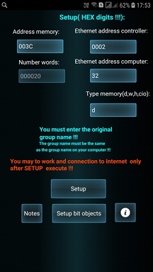
Fig. 0 - The screen for setting the Ethernet address of the computer;
Fig. 1 - The main screen of the smartphone;
Fig.2 - The screen for setting memory addresses and going to the screens for adjusting variable values;
Fig.3 - The screen for adjusting variables of the word type;
Fig. 4-The screen for adjusting bit variables;
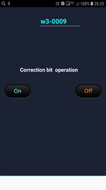
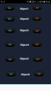
Fig. 5-The screen for setting the values of bit objects;
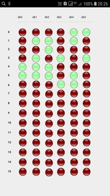
Fig.6 – Screen work with variables in the bit word (SwitchBox) ;
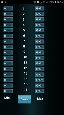
Fig.7 Screen set the minimum and maximum values for the control variables on the margins ;
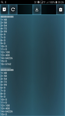
Fig.8 - Screen display of variables in the Memo and write / read Memo to the file;
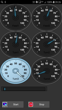
Fig.9 - Screen display of 6 variables on the scoreboard;
Fig.10 - Screen oscilloscope 6 variables ;
Fig.11 – the Screen display static graphics 6 variables;
Fig.12 - Screen editor;
Fig.13 - the Setup Screen ;
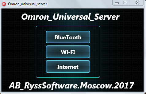
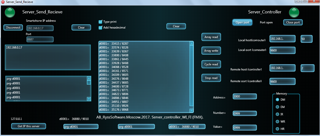
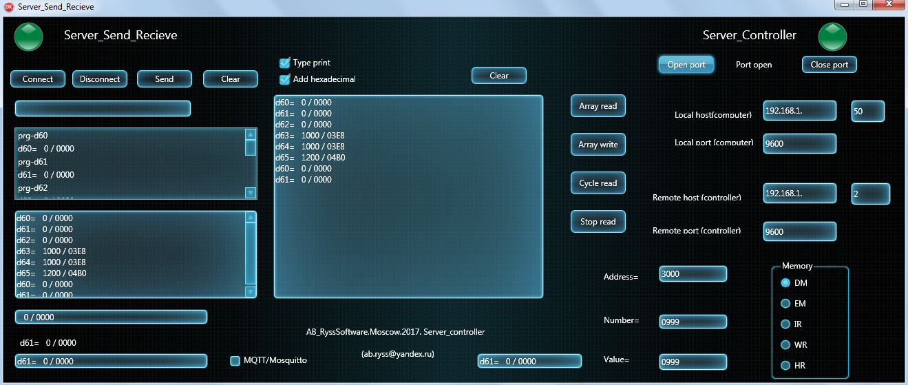
Fig.14 - screen sharing server computer
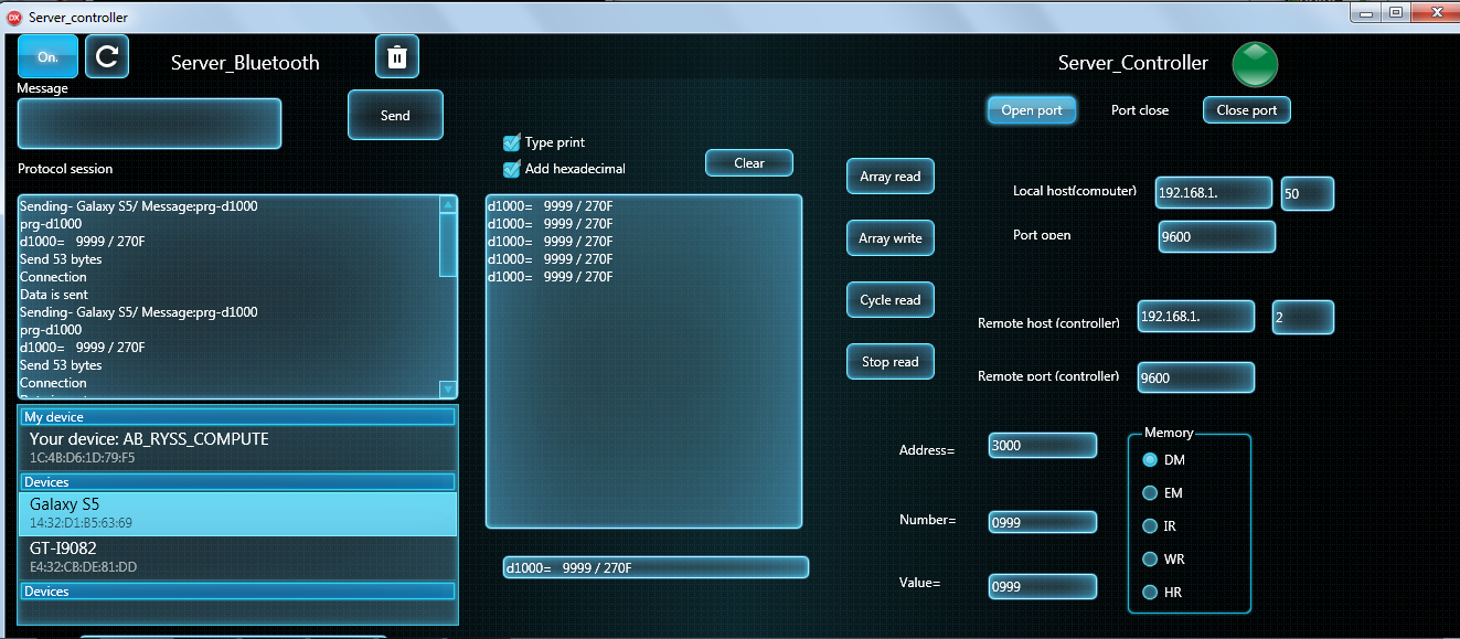
Fig.15 Server PC Bluetooth ;
Fig.16 Server computer on the WI-FI
Fig.17 Server-based computer to the Internet (MQTT);
 Send me E-mail