1.1. The Yaskawa_remote_control program is designed to exchange information between an Android smartphone
and controllers of the Yaskawa family (MP2300, MP2600, MP3300...).Communication is carried out via
the computer on which the management software server operates.
Communication between the computer and the controller is carried out over the Modbus/TCP network .
The connection between the smartphone and the computer is carried out over the Internet (MQTT broker).
The app is designed for the following technologies:
- IoT;
- Remote control;
- Remote diagnostics.
- Start-up and adjustment work on the object, when the adjuster
must be away from the control cabinets of the object;
- Generating relevant information about the object for
service personnel and management of the enterprise.
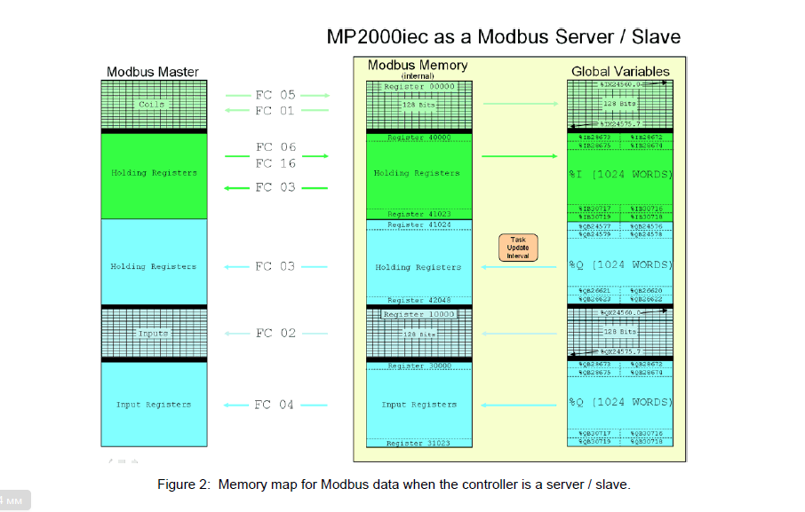
When developing the application, the standard procedure is used
Modbus/TCP - Master-Slave communication with
using the standard areas of exchange of information
FC05, FC06, FC04.
The following functions are implemented on the smartphone:
- Modes of writing/reading words Holding register (FC06);
- Input register (FC04) word reading modes;
- Write/read modes of Coil bits (FC05),
- Setting the parameters to the required exchange values
information between the smartphone and the controller;
- Write / read an entire word of memory by the user's command;
- Write / read a bit of memory by the user's command;
- Cyclic reading of variables of a single memory zone
controller (main mode);
- Cyclic control of the specified memory variables
the controller's minimum and maximum limits in
real-time signal generation at
going beyond the limits-Alarms (controlled limits
set by the user). If necessary
automatic generation of an E-mail to a user with
a failure message at the required internet address.
- Quick variable value adjustment-memory word
of the controller, in real time;
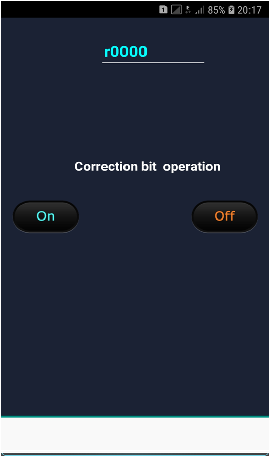
- Quick adjustment of the value of a variable – bit memory
of the controller, in real time;
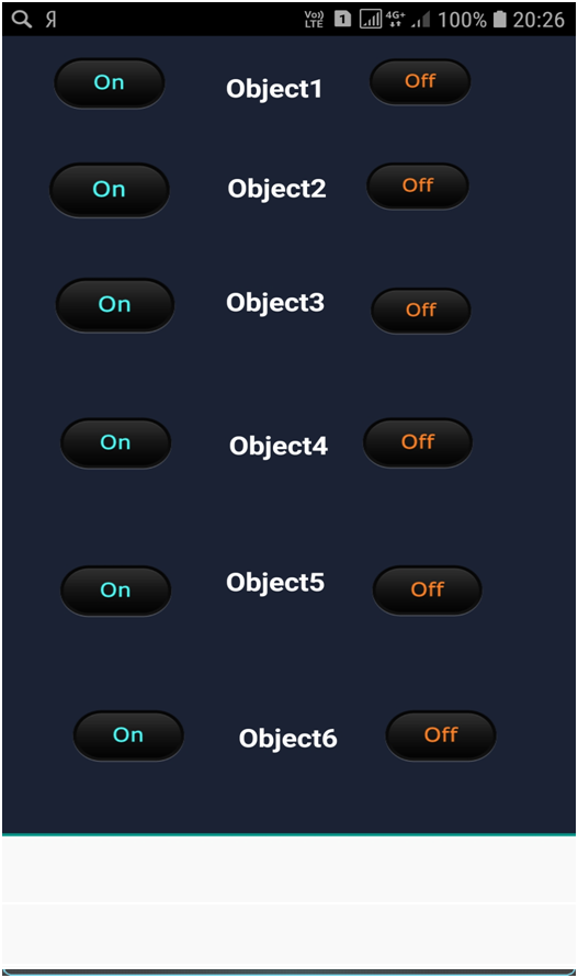
- Installing and working with controller bit objects
(the installation is performed once when you first log in to
the program and may not change further);
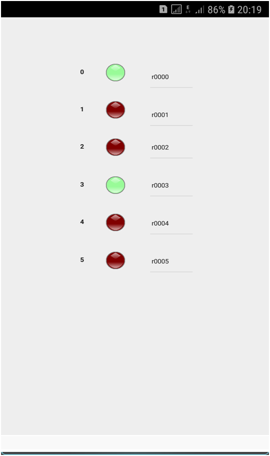
- Working with word bits – Reading / writing graphic
display of coil bits-similar to the SwitchBox program
(OMRON), in real time;
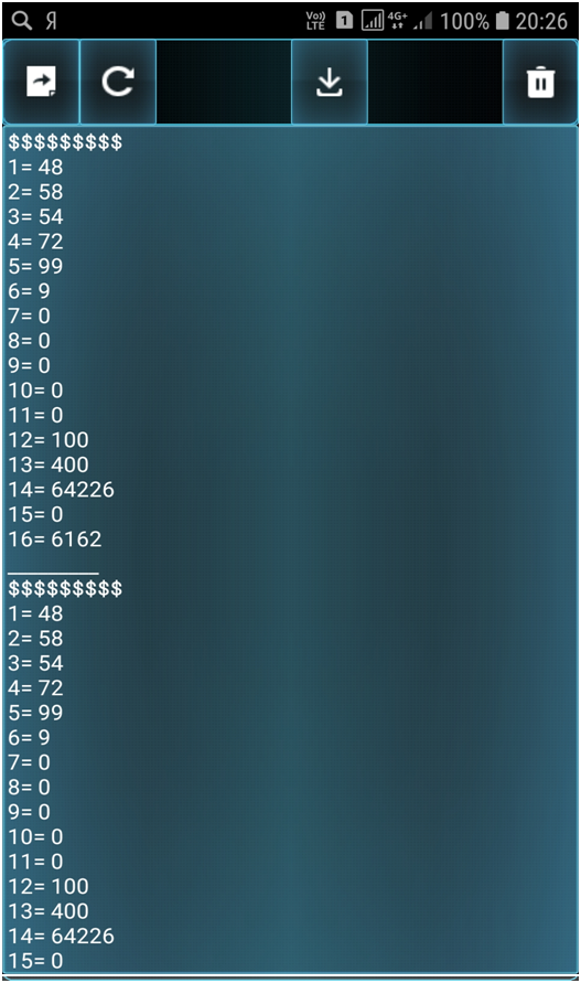
- Display of variables accepted in the loop in a separate
Memo in real time, with the ability to write
add the Memo content to the file and select the file content in
Memo.
- Display of 6 variables on the indicator board with
the ability to generate color signals, if the values
variables go beyond the required limits in real
time scale;
- Formation of waveforms of 6 variables in real
time scale. Period time =0.5...1 sec;
- Formation of static graphs of 6 variables in
in real time . Period time =0.5...1 sec.
Recording time-up to 4 hours
- Working with the built-in file editor;
etc.
1.2 . The Yaskawa_remote_control program consists of 2 parts:
- Yaskawa_remote_control. apk-implemented on a smartphone;
- Server_send_recieve.exe-implemented on the computer;
The application is developed in DELPHI XE10 (Embarcadero)
using 2 other software packages
manufacturers.
It should be noted that this program has 2 versions of the server operating on
the computer.
According to the first option, the driver must be installed on the computer
Modbus / TCP (OMRON-Yaskawa), included in the package
this software package.
Without installing this driver on your computer - this application is for this option
it won't work !!!
According to the second, more modern version, the exchange driver is already built into the program and does not require
additional installations.
Obviously, this application can be easily extended and
adapted to the specific requirements of a particular Customer.
This application is paid. The cost of the app (without listing) is $ 200 USA.
The cost of the application (with a listing) is equivalent to the salary of a high-level programmer for 3 months.
If you have any questions about purchasing the program, please contact the author at
E-mail ab.ryss@yandex.ru
1.3. The work of the applications was tested at facilities in Ukraine and India ( pipe rolling mills of the HPT series)
running Windows XP and Windows 7 ,Windows 10 and on
Samsung smartphones, Phillips running the Android 5.0...8.0 operating system.
There is a detailed description of the application in Russian and English.
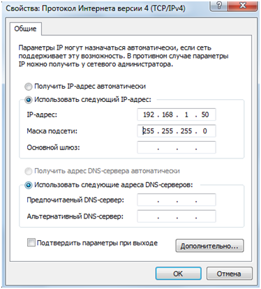
1.4 Obviously, the user does not need to have any special knowledge about setting up computer networks.
The corresponding smartphone and computer only need to be connected to the Internet.
By default, to communicate with the controller over Ethernet ( Ethernet/IP), the computer must be configured at
the address 192.168.1.50 .
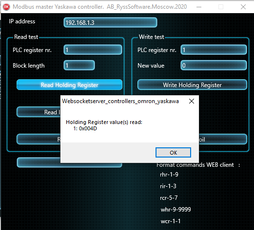
The default controller should be configured to address 192.168.1.3.
The network addresses of the computer and the controller are configured according to the Yaskawa rules .
It is also obvious that the corresponding addresses can be changed.
Before starting the exchange of information, the corresponding networks must be turned on ,the smartphone
must be turned on, the computer and the controller must be connected via the network.
Modbus/TCP with the corresponding cable, the corresponding exchange addresses are configured
over the Modbus/TCP network. There is a possibility of autonomous exchange of information between
a computer and a controller, without using a smartphone.
1.5 Below are screen shots of the computer and smartphone screens of this application:
Fig. 0 - Structure of the Modbus/TCP communication between the computer and the controller.
Fig. 1 - The screen for setting the computer's Ethernet address;
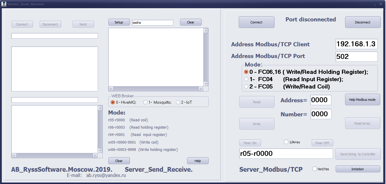
Fig. 2_1 – The general screen of the Server_send_receive program.computer exe (exchange using the OMRON driver-var. 1);
Fig. 2_2 – The general screen of the Server_send_receive program.the computer's exe (exchange using with the help of resp. component - var. 2);
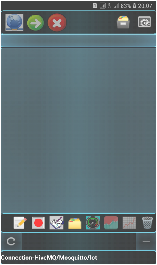
Fig. 3-The general screen of the Yaskawa_remote_control application of the smartphone;
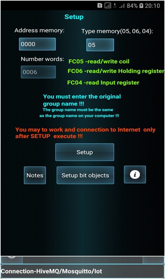
Fig. 4-The Setup screen of the smartphone;
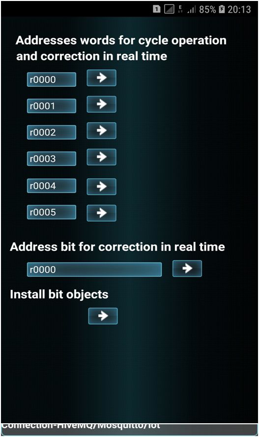
Fig. 5-The screen for setting memory addresses and going to the screens for adjusting variable values;
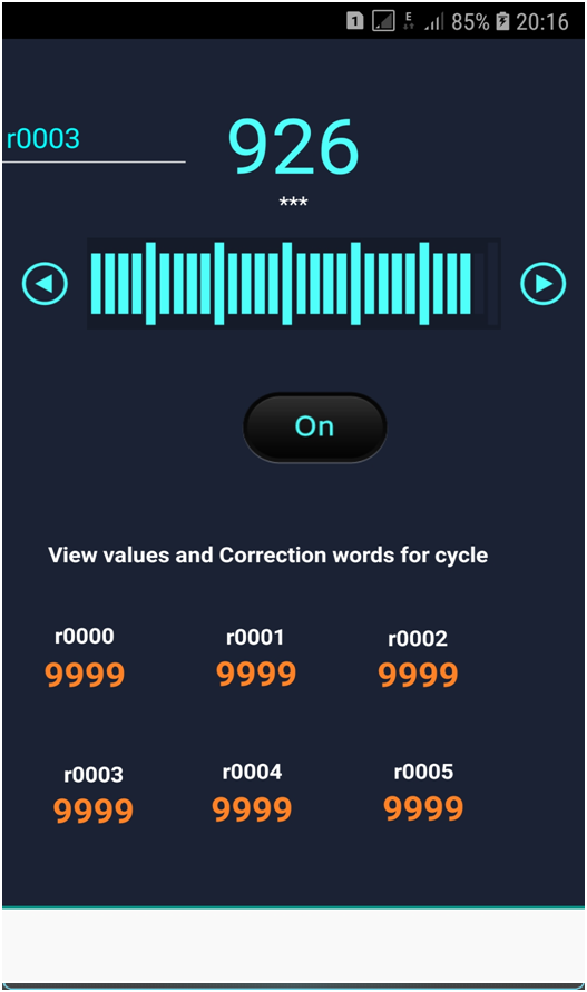
Fig.6 – Screen adjustments variable of type word;
Fig.7 – Screen adjustments of bit variables;
Fig.8 - Screen set bit object;
Fig.9 - Screen work with variables in the bit word (SwitchBox);
Fig.10 - Screen display of variables in the Memo and write/ read Memo to the file;
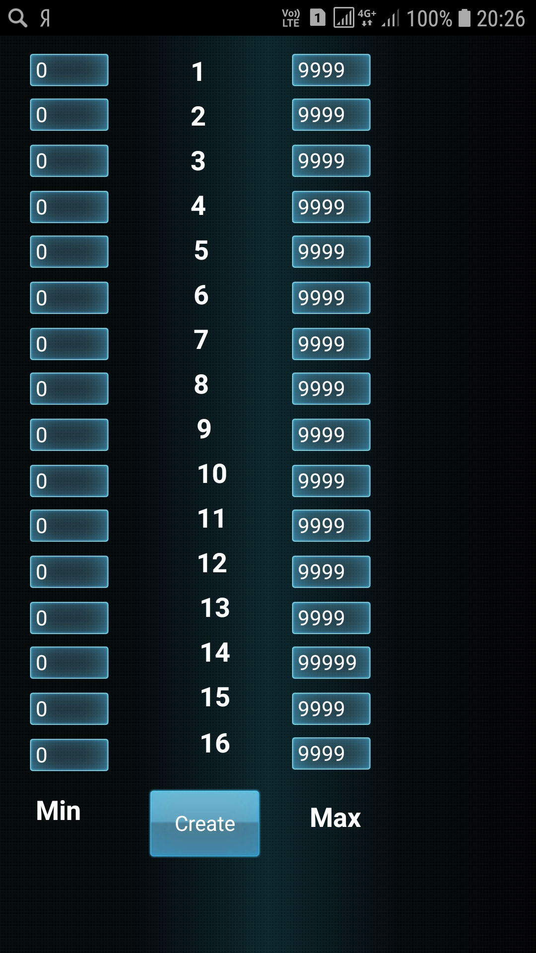
Fig.11 – the Screen set the minimum and maximum values for the control variables on the margins;
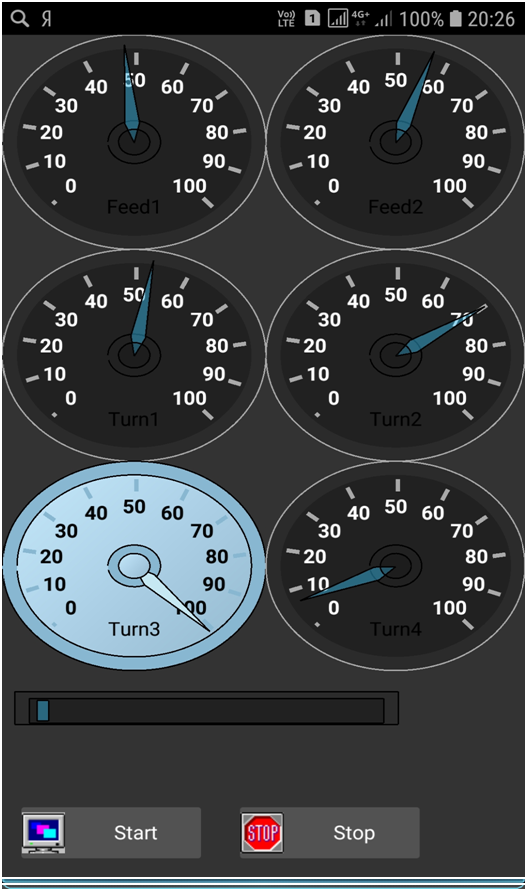
Fig.12 is a Screen display of 6 variables on the scoreboard;
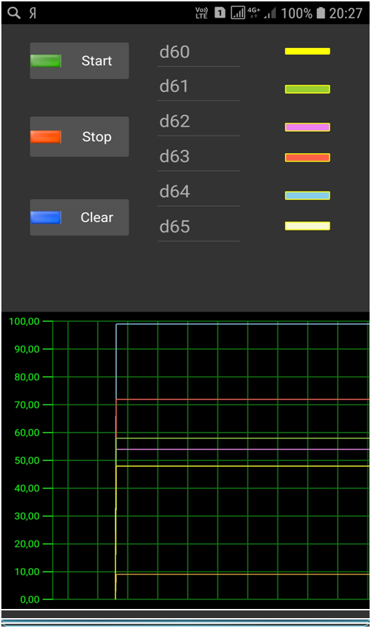
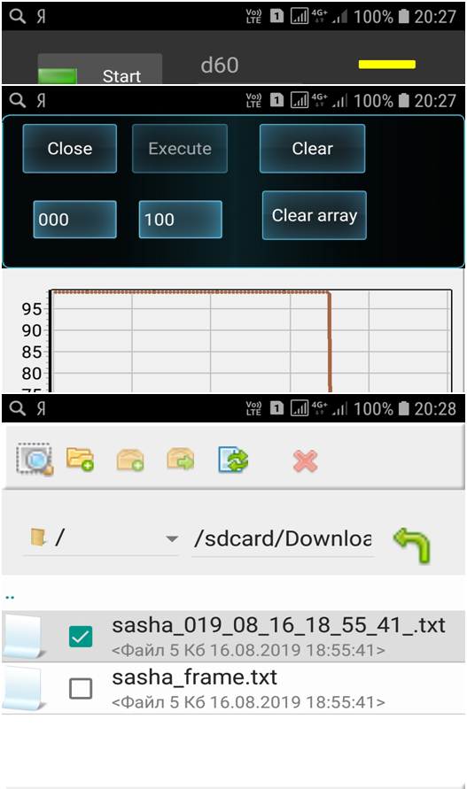
Fig.13 - Screen oscilloscope 6 variables;
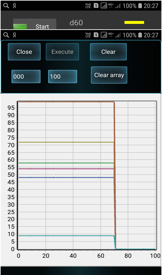
Fig.14 - Screen display static graphics 6 variables;
Fig.15 - Screen editor;
 Send me E-mail